Acceleration Data Structures
Ray tracing against a mesh becomes expensive if every ray is tested against every primitive. A model with many triangles, tetrahedra, or other mesh elements needs an acceleration structure so most primitives can be rejected before the more expensive ray-primitive intersection tests are performed.
XDG relies primarily on BVH-based acceleration structures. In keeping with the XDG design philosophy (XDG Design Philosophy), these structures are built and traversed by the selected ray tracing backend, which is separable from the supported mesh backends. On CPUs, XDG currently relies on the Embree ray tracing kernels for BVH construction and traversal.
Axis-Aligned Bounding Boxes
The basic building block of these data structures is an axis-aligned bounding box (AABB). An AABB is a conservative box around a primitive or group of primitives, aligned with the coordinate axes. Ray-box intersection is much cheaper than ray-primitive intersection, so a ray that misses an AABB can skip everything inside it.
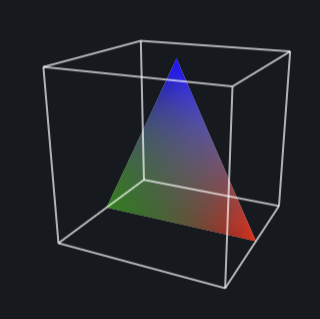
Axis-aligned bounding boxes provide simple bounding volumes for ray intersection tests.
Bottom-Level Acceleration Structures
A BLAS is a lower-level acceleration structure built over the primitives of one piece of geometry. In practice, this is commonly a BVH: leaf nodes reference primitives, while internal nodes store AABBs that enclose their child nodes. Traversal starts at the root of the tree and only descends into child boxes that the ray intersects. The diagram below shows a simple BLAS with AABBs at each node and triangles at the leaves:
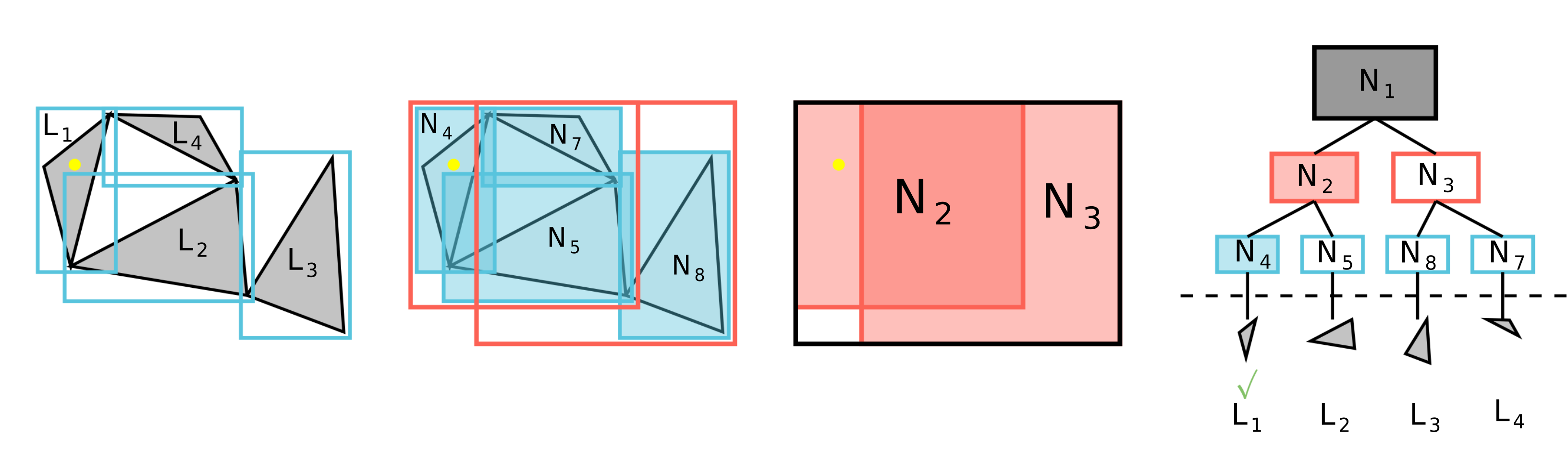
A BLAS partitions geometry into a hierarchy of bounding volumes.
Top-Level Acceleration Structures
Many ray tracing libraries use a two-level acceleration structure made from a TLAS and one or more BLASs. The TLAS itself contains only references to these BLASs, which means individual BLASs can be used across multiple TLASs. Since they reference the whole data structure rather than individual mesh primitives, a ray can first traverse the TLAS and reject whole sections of geometry if it misses the associated BLAS. It then only traverses into the relevant BLASs that the ray intersects, making tree traversal more efficient after large regions have already been culled by TLAS traversal. The diagram below shows a simple TLAS with two BLASs:
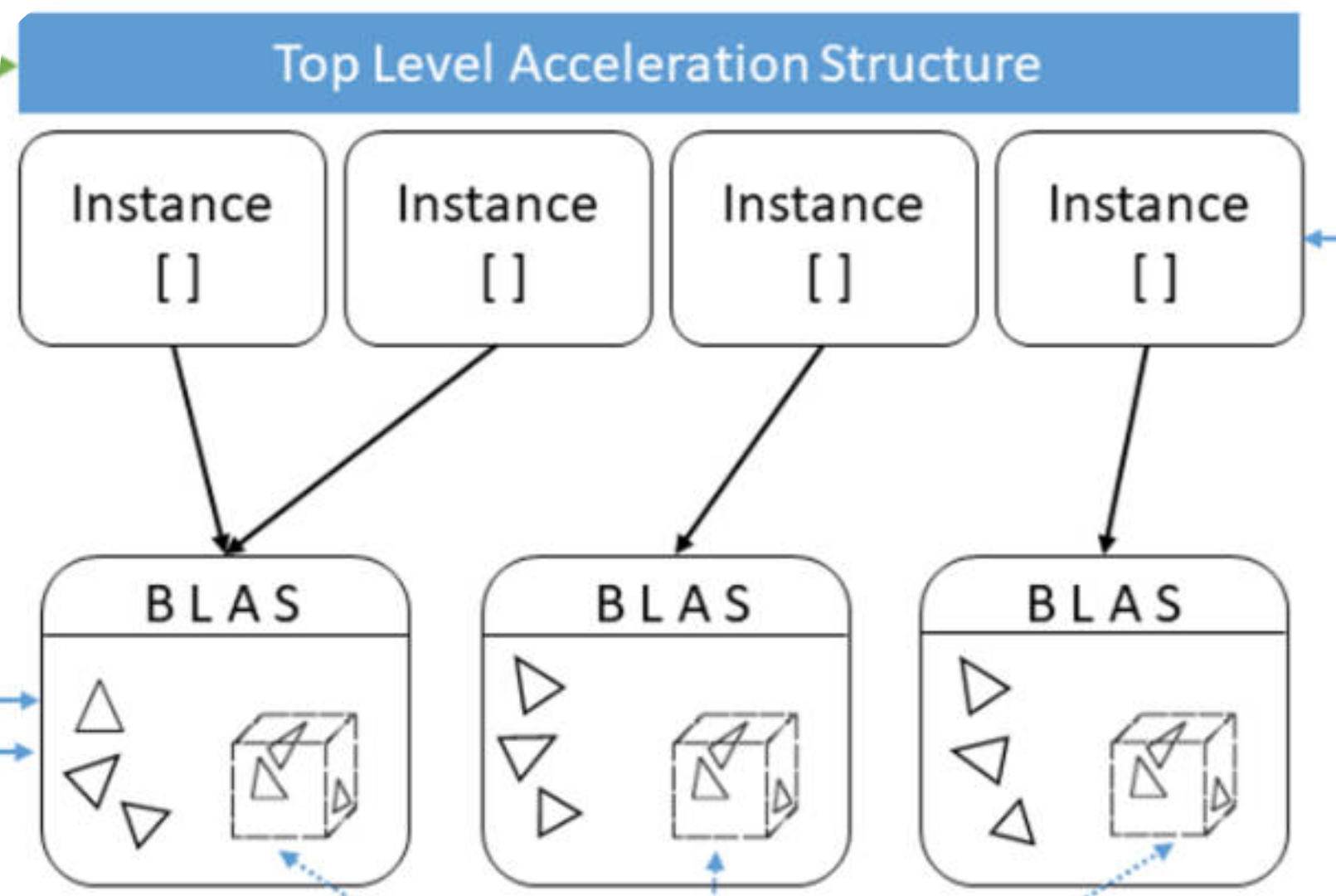
Khronos illustration of a TLAS over lower-level BLASs.
Mixed Precision Ray Tracing
The paper "Hardware-Accelerated Ray Tracing of CAD-Based Geometry for Monte Carlo Radiation Transport" discusses the use of mixed-precision algorithms to efficiently handle complex CAD-based geometries in Monte Carlo radiation transport simulations. The key contributions of the paper include leveraging modern ray tracing kernels to significantly speed up the ray tracing process, which is critical for handling the high computational demands of Monte Carlo methods [1].
By integrating the techniques discussed in the paper, XDG achieves faster BVH construction and traversal, leading to more efficient simulations. This is particularly beneficial for applications involving complex geometries and large-scale simulations, where traditional CPU-based methods may fall short in terms of performance.
GPU-Accelerated Ray Tracing
Ray tracing as a technique is highly parallelizable and has been extensively optimized for GPU architectures in the context of graphics rendering. As a result, there is a rich ecosystem of GPU-accelerated software and even specialized hardware (see RT hardware acceleration) for ray tracing operations. Historically, these capabilities have focused on single-precision support and have not typically been adopted in the scientific computing community.
XDG is intended to support GPU acceleration and provide an interface for leveraging GPU-accelerated ray tracing in scientific computing applications. An explicit focus is being placed on vendor-agnostic GPU support to ensure that XDG can be used across a wide range of hardware platforms. Currently, initial scoping of the GPU API is underway with work being done to support GPRT (General Purpose Ray Tracing Toolkit), a Vulkan-based GPU-only ray tracing library that is vendor-agnostic and built around the Vulkan API. Other GPU ray tracing libraries will also be explored in the future, with the eventual goal of providing complete feature parity between CPU and GPU backends of XDG.
Backend Terminology Mapping
The BLAS/TLAS terminology is useful for describing the common two-level
acceleration structure pattern, but XDG does not require every backend to expose
explicit BLAS and TLAS objects. In XDG's Embree backend, RTCGeometry maps
functionally to a BLAS and RTCScene maps functionally to a TLAS. Embree
still builds the concrete acceleration structures internally when those objects
are committed, and the current XDG Embree backend attaches geometries directly
to scenes rather than using Embree instance geometries. Conceptually, the
BLAS/TLAS terminology still applies, while a GPU library like GPRT represents
the BLAS/TLAS and instancing model more explicitly.
For surface tracking, XDG traces against the boundary surfaces of a topological volume where each surface has its own BLAS:
Concept |
Embree |
GPRT |
|---|---|---|
TLAS |
|
|
BLAS |
|
|
Instancing |
Not used currently; |
|
Topological volume |
Per-volume |
TLAS over the BLASs for the volume's boundary surfaces |
Topological surface |
Cached |
|
For volume tracking, XDG traces against the volumetric elements inside a topological volume where each volume has exactly one BLAS containing all of its elements. In the current Embree backend this is a one-geometry-per-scene mapping. Volumetric tracking has not been implemented with GPRT yet, so the table below reflects the intended TLAS/BLAS mapping:
Concept |
Embree |
GPRT |
|---|---|---|
TLAS |
|
|
BLAS |
|
|
Instancing |
Not used currently; the volume |
|
Topological volume |
Per-volume |
TLAS over the volume-element BLAS instance |
Topological surface |
Part of the topology, but not represented in this volume-element BLAS/TLAS mapping |
Part of the topology, but not represented in the volume-element BLAS/TLAS mapping |